So, this is what I got when it arrived. I did a visual inspection without knowing the radio or scanning the schematic first.
Not too bad looking at first sight.
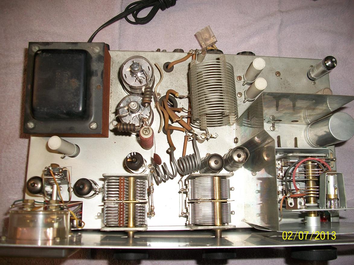
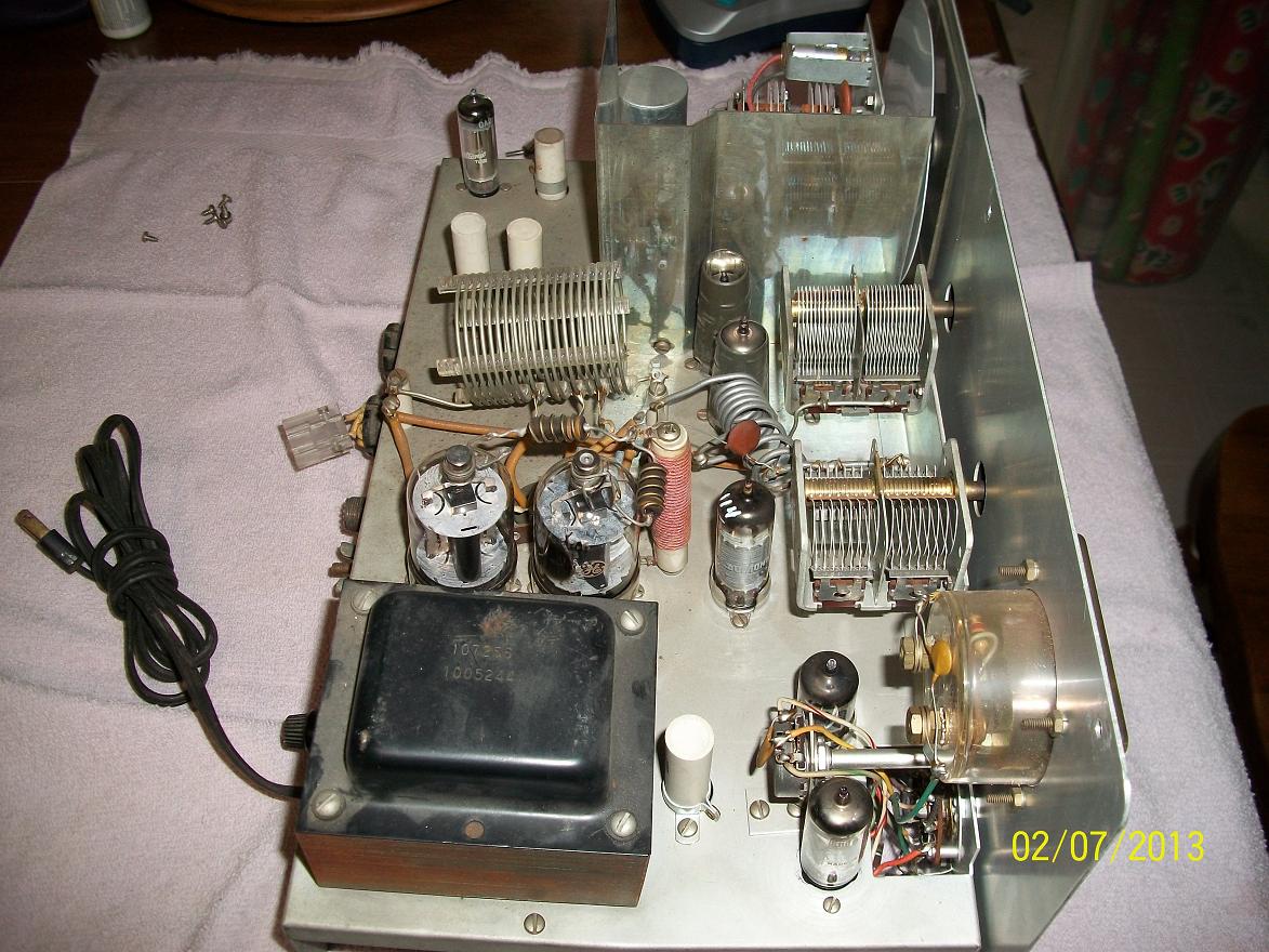
The top looks pretty clean and nicely put together.
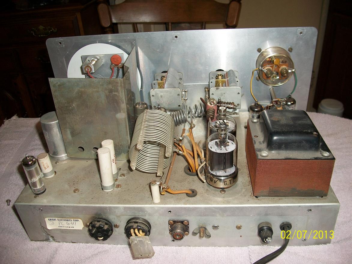
Another view still shows a clean looking transmitter and the chassis is not to pitted..
Clever ideal to put a plug on the socket to provide receiver muting.
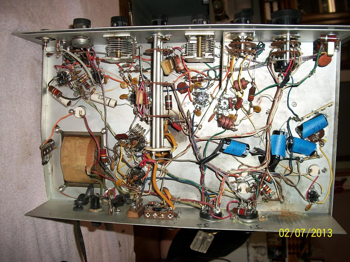
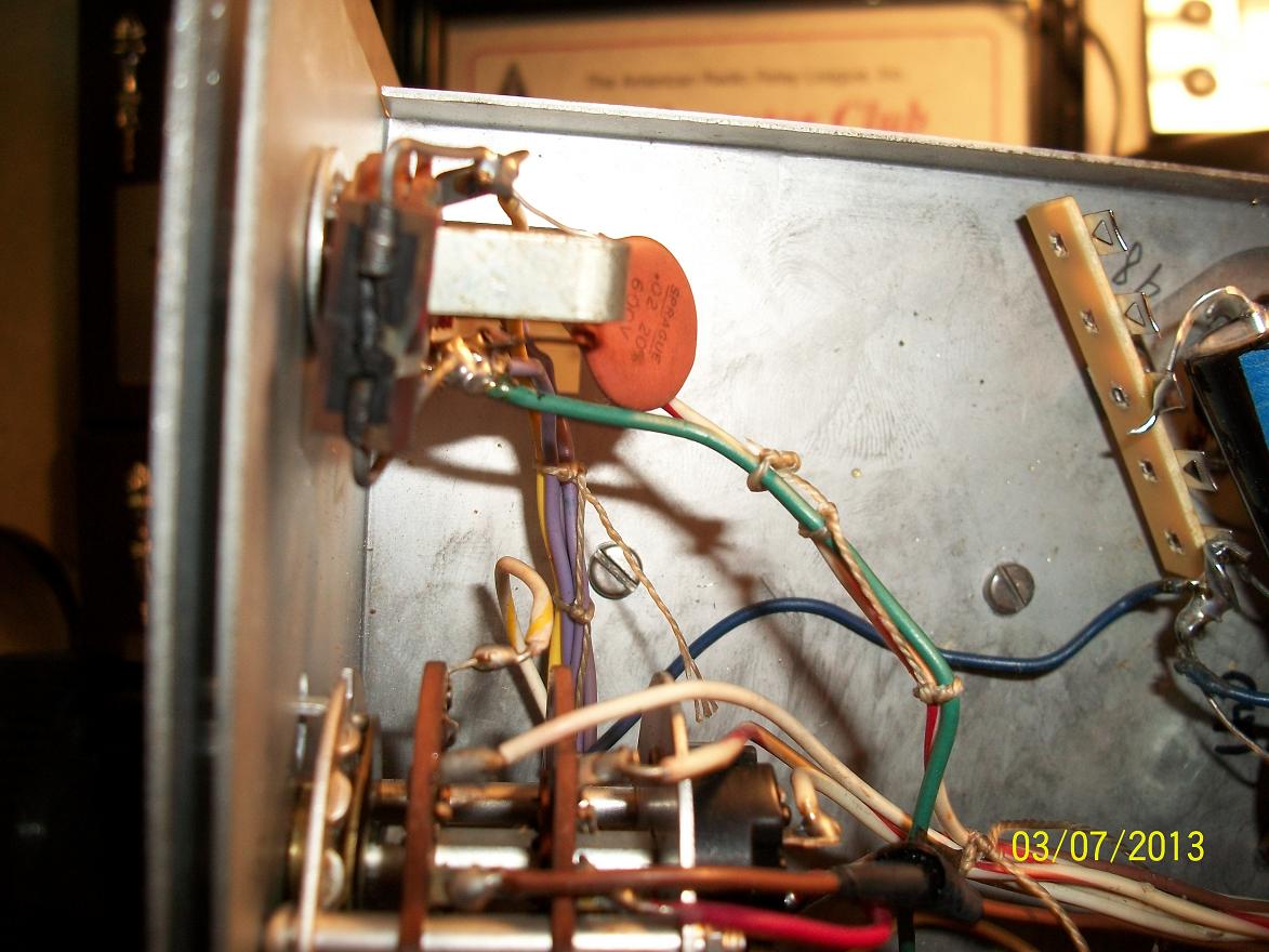
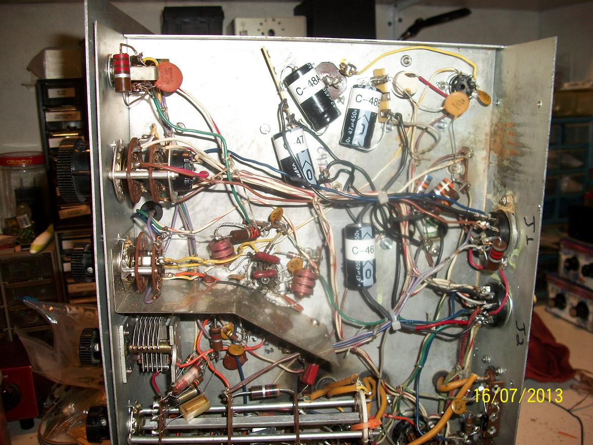
Now under the chassis is where things get ugly FAST!
Notice the burn spot (most likely from the can cap shorting) near the back of the band switch, and a piss poor attempt to replace the can cap in the power supply.
There are bad solder joints, electrical tape used to cover wires that were extended. I've seen better work done on modified CB radios.
After making sure nothing was shorted and look reasonably good, I plugged in the transmitter, turned it on, and put it in standby.
I went through the tune up procedure, it's a bit cumbersome than most radios of this vintage but not too bad.
I waited 30 minutes to make sure all was fine, then started the tune up. Three steps in I was not getting power out and the oscillator was not running. Then it went POP!
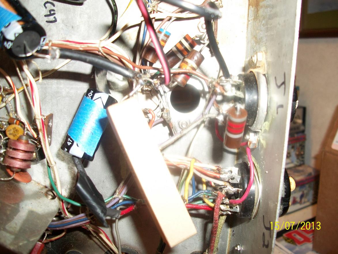
I noticed the Plate current pegged right before the pop. Upon inspecting the radio I saw the resistor on the key jack had blown up, one of the 150 ohm\20W resistors in the power supply cracked open, and R21 that goes to the 12BY7 was also blown.
I was to say the least mad as hell! I was told by the seller he tested it, got 60W out on AM and no further testing was done. When I asked him after it blew, he then said it worked well and he had several Q's on Am with local Hams. Bottom line, he's full of BS.
He did refund me some money even though he wanted me to return the radio, but the face of this rig is near perfect, and I knew I could repair it.
I pulled together some parts that were close enough in value from the junk box, fixed some wiring mistakes, and cleaned up a lot of bad solder joints.
I wanted to see if there was hope for this radio.
The results were good, output was a bit low at 60W in CW, but not knowing what else was messed up and not using the proper value replacement parts, it tuned up well and there was hope!
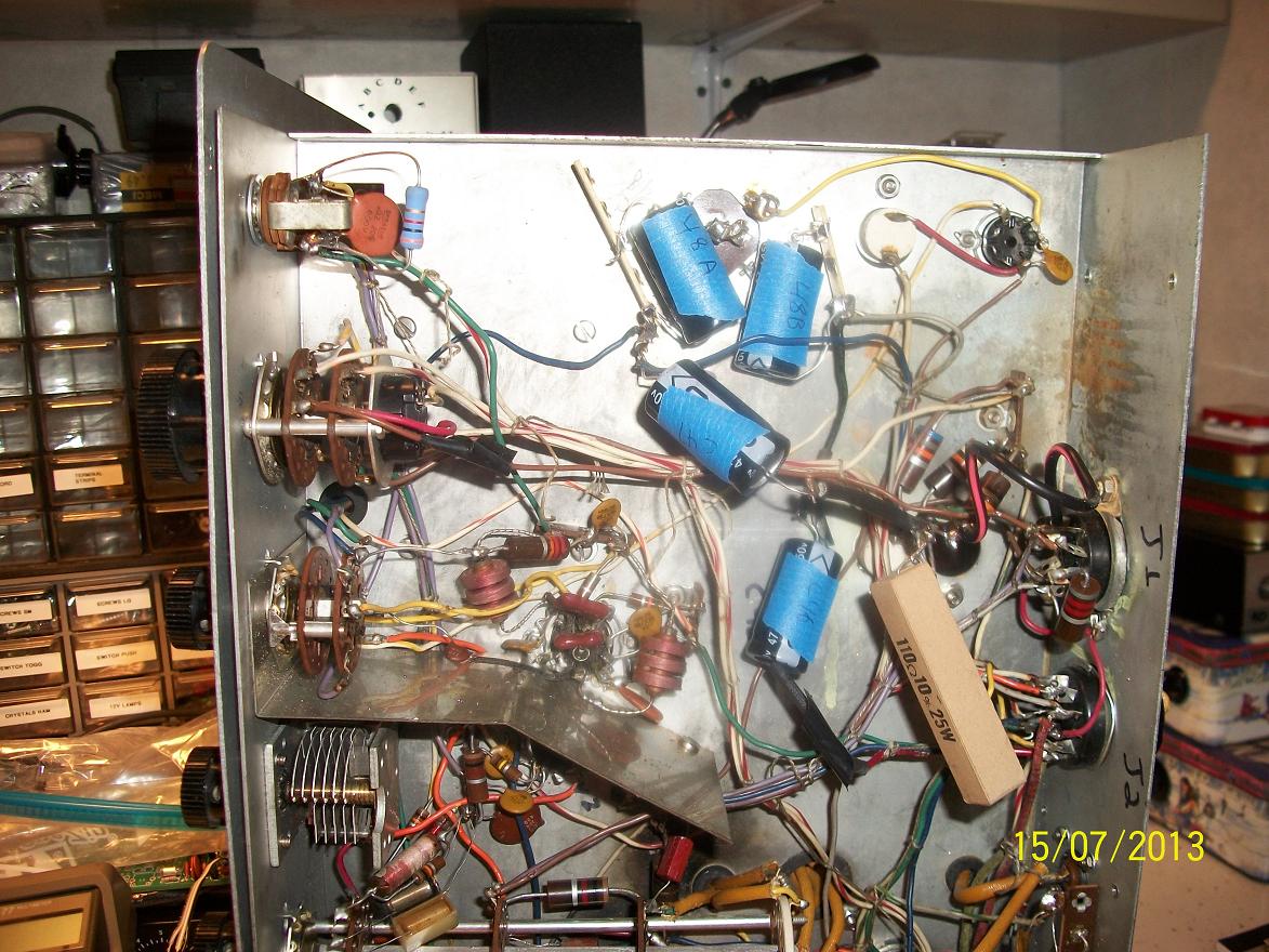
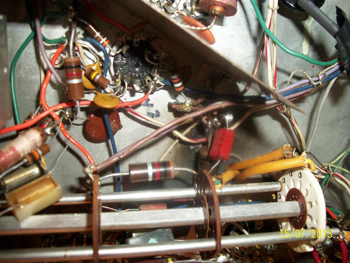
This picture gives you an idea of just how badly this radio was built or repaired.
So off to the internet and some part shopping. At this point I only needed a 2.2K[3W resistor, a 2.2K\2W resistor, and I decided to replace both 150\20W resistors. I also noticed that near the rear of the band selector where the burnt area was, ran R10, a 10\3W resistor. I decided to replace it because it fed right to the plates of the 6146's.
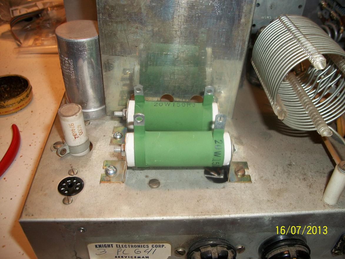
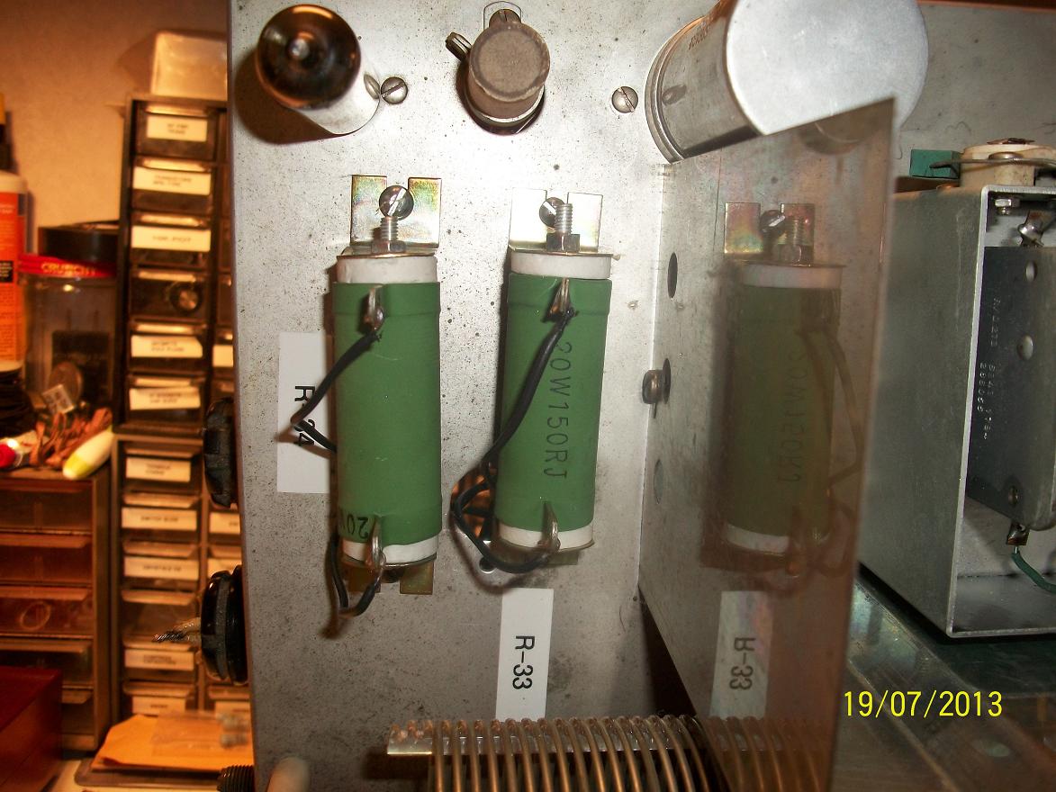
Once I got all my parts together, the first thing I did was unwire the power supply and install the new 150\20W resistors. These are different than stock and block the VFo adjustment screws when installed.
A small price to pay for bigger and beefier resistors!
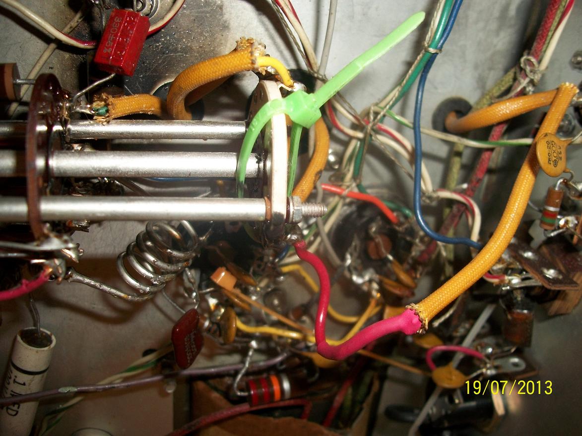
Next on to the rewiring. I tried to make things a bit neater, fixed the soldering, and shorten the leads where possible. It was during this part I found C49 a .005pf cap missing.
Here is the result, better but not to my standards, but I did not feel like re-kitting this radio, it was just not worth the bench time.
Here are the power resistors wired and labeled.
After a few hours and several breaks to clear my head it was finished. I decided to do a once over before applying power and glad I did. I found the rear wafer of the band switch was broke in two. It turns out it was a good break and with a wire wrap it held in place good enough to test. I'll have to fix this before I put it back in the case.
I used JB Weld and a wire tie to secure the the rear wafer while it set up.
I paired it up my a Hallicrafters SX-122, then I let it warm up for an hour and went through the tune up process.
This time it went by the book. PO in CW is just a tad over 100W, and in AM it's around 12W. I did an alignment on the VFO and got it just about perfect with the dial display.
I made a CW QSO and got a good report (I'm using my old Vibroplex Lightning Bug), then fired up the 3 tube 811 amp for AM. it drives the amp at 115W carrier and drives up to near 500W! Using an amplified D-104 mic I had a nice round table QSO on 7.295. I was given great signal and audio reports.